Electromagnetic Induction Class 12 | Notes | Chapter 6 | Physics | CBSE |
Table of Contents
Electromagnetic Induction Class 12 | Chapter 6 | Physics | Class Xll | CBSE |
The phenomenon of generating induced emf or induced current into a closed circuit due to change in strength, position or orientation of external magnetic field is defined as electromagnetic induction.
Magnetic Flux
It is defined as number of magnetic field lines passing through the area vector.
Let A be area vector which is normal to the plane of surface
B be uniform magnetic field
θ be angle between area vector and magnetic field
Magnetic flux (Φ ) = B . A = B A cosθ
→ When Magnetic field is normal to the surface then angle between area vector and magnetic field is 0°. Φ = B A cos 0° = BA
→ When Magnetic field is tangential to the surface then angle between area vector and magnetic field is 90°. Φ = B A cos 90° = 0
→ SI unit of magnetic flux is Weber (Wb) and its CGS unit is Maxwell (Mx) .
1 Weber = 108 Maxwell
→ It is a scalar quantity.
→ Dimensional formula of Magnetic flux is [M L2 T-2 A-1]
Faraday’s Law of Electromagnetic Induction
Faraday’s First Law
It states that when magnetic flux linked with changes, an e.m.f is induced in it which lasts as long as change in flux is continued.
Explanation: When a magnet is moved towards or away from the coil, galvanometer shows deflection. This deflection indicates that emf is induced in the coil.
On the other hand, when magnet is not in any relative motion with coil, magnetic flux linked with it remains constant and galvanometer shows no deflection.
Faraday’s Second Law
The rate of change of magnetic flux is directly proportional to induced emf in a closed loop or circuit.
e ∝ dΦ / dt
e = –N (dΦ / dt)
Negative sign indicates that induced emf in the loop is always opposes change in magnetic flux associated with it.
Induced Current in the coil, I = induced emf / Resistance of coil = | e | / R = N (dΦ / dt) / R
I = N (dΦ / dt) / R
Lenz’s Law
According to Lenz’s law, direction of induced emf is such that it always opposes the cause that produces it. It is based on law of conservation of energy.
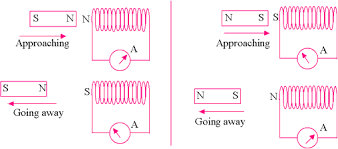
Case 1: When north pole of magnet is moving towards the coil, magnetic flux linked with it increases and direction of current will flow in such a way that it opposes the movement of North pole, so it has to act as North pole.
Case 2: When north pole of magnet is moving away from the coil, direction of current will flow in such a way that it opposes the movement of North pole, so it has to act as South pole.
Question : The current flowing is in the direction from Y to X and is decreasing. What would be the direction of induced current in the magnetic loop which is placed near the wire?
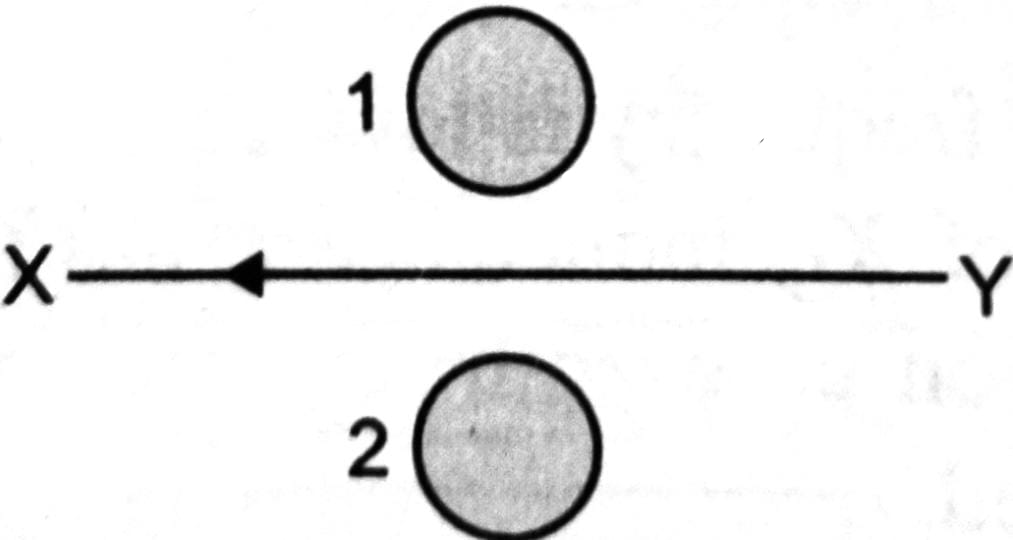
Solution : According to Lenz’s law, the induced current in ring 1 will be in clockwise and in ring 2 it will be anticlockwise direction.
Question : As soon as the current is switched on in a wire carrying a high voltage, the bird sitting on it flies away. Give reason.
Solution : When current is switched on in a wire magnetic flux linked through the bird changes and hence induced current flows through the bird’s body. Due to presence of opposite current, its wing experiences mutual repulsion and spreads and hence flies away.
Question :Mention the ways through which emf can be induced.
- By changing Area enclosed by coil
- By changing orientation of coil
- By changing the magnitude of magnetic field B
- By changing the angle between direction of B and Area vector
Motional Electromotive Force (Translatory Motion)
Let l be the length of conducting rod
B be the uniform magnetic field
v be the velocity of rod
![]()
Each positive charge q which is within the rod moves with a velocity v and experiences a upward force F = q (v x B) while the negative charge or electron experiences a downward force. Hence, P side attains +ve charge while Q side becomes -ve . As a result, electric field is set up from P to Q.
Downward force by electric field is balanced by magnetic field.
FE = FB
qE = q (v x B)
(Electric Field) E = v x B
→ Induced Emf = Potential = Electric Field x length
e = vBl
e= Blv
This is the required expression for emf induced in rod.
→ Induced Current = Induced Emf / Resistance
I = Blv / R
→ Force experienced by rod = BIl = B (Blv / R) l
F = B2l2v / R
→ Power = Force x Velocity
Power = (B2l2v / R) (v)
Power = B2l2v2 / R
→ Induced charge on rod
e = IR = ( dQ / dt) (R)
Also , e = dΦ / dt
dΦ / dt = ( dQ / dt) (R)
dQ = dΦ / R
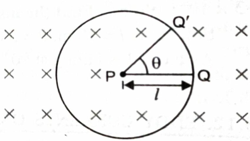
Motional Induced e.m.f. in a Conducting Rod Rotated in a Uniform Magnetic Field
Let l be the length of conducting rod
ω be the uniform angular velocity
B be uniform magnetic field directed into the paper
Crosses represents the uniform magnetic field with inward direction
Area swept by the rod will be given as A = (1/2) (l) (lθ) = 1/2 l2 θ
Induced emf = dΦ / dt
e = d/dt (B.A)
e = d / dt [B . (1/2 l2 θ) ]
e = (1/2) (B l2 ) (dθ / dt)
e = (1/2) B ω l2
Eddy Current (Focault Current)
Eddy Current are current induced in the piece of conductor (sheet) when magnetic flux changes with respect to it.
Though Eddy current can be reduced, but it is impossible to permanently remove eddy current.
These are also known as Focault Current.
Applications of Eddy Current
- Electromagnetic Damping : It is a damping technique in which electromagnetic current slows down the motion of an object without any actual touch. It can be decreased by decreasing the area.
- Induction Furnace
- Magnetic Brakes
- Electric Power Motors
- Induction Motor
- Speedometers
- Magnetic Brakes
Methods of Reducing Eddy Current
- By lamination of sheets which reduces possible energy loss in the form of heat
- By cutting the sheets or making slots in it.
Self Induction
It is the property of a coil by virtue of which it opposes any change in strength of current flowing through it by inducing an emf in itself.
Co-efficient of Self Induction
It is numerically equivalent to the amount of magnetic flux linked with the coil when unit current flows through the coil.
e = -L (dI / dt)
e = -L x 1
L = -e
Self Inductance of a Long Solenoid
Let N be number of turns of coil
l be length of core of solenoid
μo be magnetic permeability in free space
A be area of each turn
Magnetic field due to a solenoid; B = μo NI / L
Total Area = NA
Total Magnetic flux = Magnetic flied x total Area
Φ = ( μo NI / l) (NA )
Φ = LI
LI = ( μo NI / l) (NA )
L = μo N2 A / l
Mutual Induction
The property of coil by virtue of which it opposes any change in strength of coil placed near to it when magnetic flux linked with it changes.
Co-efficient of Mutual Induction
It is numerically equivalent to the amount of magnetic flux linked with one coil when unit current flows through the neighbouring coil.
Let I be total current in first coil
Φ be total amount of magnetic flux associated with neighbouring coil
Φ ∝ I
Φ = MI
M is a constant of proportionality and is commonly known as Coefficient of Mutual Induction
The SI unit of M is henry.
1 Henry : The two coils are said to have a mutual inductance of 1 henry if an emf of 1 volt is induced in one coil when current flowing through neighbouring coil is changing at the rate of 1 ampere / second.
Factors on which Mutual Induction Depends
- Distance between the coils
- Geometry (Shape , Size , No of turns , Nature of material)
- Orientation of Coil., i.e, relative placement of two coils
Note: The coil in which current is changed is called Primary Coil and the coil in which emf is induced is called Secondary Coil
Mutual Induction of Two Long Coaxial Solenoids
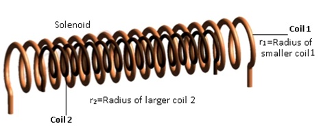
Let S1 , S2 be two long coaxial solenoids
L be length of solenoid
N1 , N2 be number of turns of respective solenoids
r1 be radius of smaller coil 1
r2 be radius of larger coil 2
Mutual Induction of S2 due to S1 (M21) = N2Φ2 / I1 ….(A)
Φ2 = B1 x A = ( μo N1 I1 / l) (A)
Substituting the value of Φ2 in equation (A)
M21 = (N2 / I1) ( μo N1 I1 / l) (A)
M21 = μo N1 N2 A / l …(i)
Mutual Induction of S1 due to S2 (M12) = N1Φ1 / I2
Φ2 = B2 x A = ( μo N2 I2 / l) (A)
M12 = (N1 / I2) ( μo N2 I2 / l) (A)
M12 = μo N1 N2 A / l …(ii)
According to equation (i) and (ii), we get
M12 = M21 = μo N1 N2 A / l
We would love your reading of Electric Charges and Fields, Electrostatic Potential and Capacitance, Magnetism and Matter, Electromagnetic Induction , Moving Charge and Magnetism, Current Electricity for scoring better and having deeper understanding of the chapters.
Do share this post if you liked the notes of Electromagnetic Induction Class 12. For more updates, keep logging on BrainyLads
Moving Charge and Magnetism Class 12 | Chapter 4 | Physics | CBSE |

Current Electricity Notes | Chapter 3 | Physics | Class 12 | CBSE | Term 1 |