Current Electricity Notes | Chapter 3 | Physics | Class 12 | CBSE | Term 1 |
Table of Contents
Current Electricity Notes | Chapter 3 | Physics | Class Xll | CBSE |
Electric Current
It is defined as the amount of charge flowing through any cross section of conductor per unit time.
Electric Current = Total charge flown / Time taken = q / t
SI unit of electric current is Ampere.
CGS unit of electric current is absolute ampere.
Ampere: When charge flowing per second through any cross section of conductor is one coulomb then current through a conductor is said to be 1 ampere.
Though Current has both magnitude and direction yet it is a scalar quantity since it does not obey vector laws.
Electric current in human nerve is of the order of microampere and and electric current more than 0.015 A through human body can be fatal.
Types of Current
Steady Direct Current : Magnitude and direction do not change with time
Variable Current : Magnitude changes with time and polarity remains same.
Alternating Current : Magnitude changes with time and polarity reverse periodically after regular interval of time.
Drift Velocity
Concept: In metal or conductor, there are extremely large number of free electrons. These electrons move randomly with a thermal speed of 105 to 106 ms-1 at room temperature.
Drift velocity is defined as the average velocity with which the electron moves from -ve to +ve terminal under the effect of external electric field.
When external electric field is applied electrons will accelerate
F = ma = -eE
a = -eE / m ….(i)
Relaxation time
The time between two consecutive collision of electron and atom is defined as relaxation time.
Let Vd be drift velocity
τ be relaxation time
acceleration = velocity / time = Vd / τ ….(ii)
Equating equation (i) and (ii)
-eE / m = Vd / τ
Vd = -eEτ / m
This is the required expression for drift velocity.
Factors Affecting Drift Velocity
Vd ∝ E (when τ is constant)
Vd ∝ τ (Relaxation time)
Vd ∝ 1/ temperature
On increasing temperature, motion of electrons increases thereby increasing collision. As a result relaxation time decreases resulting in decreased drift velocity.
Relation between Drift Velocity and Electric Current
Let l be length of conductor
A be area of cross section
V be applied potential difference
E be electric field
n be number of electrons per unit volume of conductor
Volume of conductor = Al
Total number of electrons in conductor = (Number of electrons per unit volume of conductor) x (volume of conductor)
Total number of electrons in conductor = n Al
Total Charge = Total number of electrons x e = n A l e
Speed = Distance / time
Vd = l / t
t = l / Vd
Electric Current = charge / time
I = Q / t = n A l e / t = n A l e / ( l / Vd )
I = n e A Vd
→ We know, Vd = eEτ / m
I = n e A (eEτ / m)
I = ne2 E A τ / m
→ Also, E = V / l
I = ne2 V A τ / ml
Current Density
Current density at any point in a conductor is defined as the amount of charge flowing through per unit cross section of conductor around that point in such a way that area is always tangential to the current.
Area is normal to direction of current.
J = I / A cos θ
I = J A cos θ
I = J . A
Current density is a vector quantity whose direction is along the direction of current.
→ We know, I = n e A Vd
J = I / A = n e Vd
Ohm’s Law
According to Ohm’s law; under constant temperature, pressure or mechanical strain current flowing through a conductor is directly proportional to potential difference applied across the ends of conductor.
I ∝ V
V = IR
Here R is Resistance
Electrical Resistance
Cause of Resistance: Collision between electrons and atoms during the flow of electric current.
Resistance is measured by ohmmeter.
Electrical resistance of a conductor is defined as the ratio of potential difference applied across the ends of conductor to the current flowing through it. It is opposition of flow of current.
Dimension of electric resistance is [ M1 L2 T3 A-2 ]
In Series Combination : 1 / Rs = 1/ R1 + 1 / R2 + 1/ R3 …
In Parallel Combination : Rp = R1 + R2 + R3 …
I = n e A Vd
I = n e A [ e E τ / m ]
I = ( n e2 A τ / m ) ( V / l )
m l / n e2 A τ = V / I
R = m l / n e2 A τ
On increasing temperature, relaxation time decreases thereby increasing the resistance
Resistivity
It is that property of material which explains that how much resistance is being offered by that material.
R = m l / n e2 A τ …(i)
R = ρ l / A …(ii)
Equating equations (i) and (ii)
m l / n e2 A τ = ρ l / A
ρ = m / n e2 τ
Mobility
It is defined as ratio of magnitude of drift velocity per unit electric field applied.
μ = Vd / E
μ = e E τ / m E
μ = e τ / m
Ultimately mobility depends on relaxation time
Mobility of electrons is greater than that of holes since mass of holes is slightly greater than that of electrons.
Superconductor: A metal , alloy or oxide which shows zero resistance at very low temperature are called as super conductors.
Critical Temperature: The temperature below which a material becomes super conductor is defined as transition temperature or critical temperature.
Microscopic Form of Ohm’s Law
Potential difference (V) = E x l
Also, V = IR
IR = E l
I ρ l / A = E l
E = I ρ / A
E = J . ρ
J = E / ρ
J = E σ
Here σ is conductivity and J is current density
Variation of Resistance or Resistivity with temperature

For Conductors:
Metallic conductors already have free electrons. On increasing temperature, number density of free electrons does not change appreciably. Ions of metal further vibrate with greater amplitude and thus collision between the electrons increases. This decreases the relaxation time . The value of electrical resistance for a metallic conductor increases with increase in temperature.
For Insulators or Semi-conductors :
Semiconductors or insulators does not have free electrons . On increasing temperature number density of free electron increases and hence the conductivity also increases. Thus, resistance or resistivity of semi – conductor or insulator decreases with increase in temperature.
For Alloys :
Alloy having the composition more than one material and their resistance or resistivity does not change appreciably or rapidly with change in temperature.
Temperature Coefficient of Resistance
Temperature coefficient of resistance is defined as change in electrical resistance per unit chnage in time.
Let R be resistance at certain temperature
Ro be resistance at 0° C
α be temperature coefficient of resistance
α = R – Ro / Ro (Δt)
Its Unit is ° C -1
For resistivity
α = ρ – ρo / ρo (Δt)
For metals R > Ro Thus temperature coefficient of resistance for metals is positive
For insulators R < Ro Thus temperature coefficient of resistance for insulators is negative
For Alloys ; temperature coefficient of resistance is negligible
Question : Why standard resistance are always made of alloy like manganin and Constantan ?
Answer: This is because temperature coefficient of alloys are almost negligible so on increasing temperature there is no net effect on resistance. Thus they can survive at high temperature without changing behaviour.
Internal Resistance
Resistance offered by internal part of any cell.
It is also defined as resistance offered by an electrolyte and is represented by r . It is measured in ohm .
E = V + I r
E – V = I r
r = ( E – V / V ) R
Factors on which Internal Resistance Depends
r ∝ 1 / Temperature
r ∝ 1 / Area of electrodes
r ∝ distance between electrodes
r also depends on concentration and nature of electrolyte
I = E / R + r
I ( R + r ) = E
V + I r = E
Here E is emf and V is potential difference
→ When circuit is open → No current is flowing
E = V + I r
E = V
→ When Circuit is Closed
1) Discharging
E = V + I r
V ≠ 0 , I ≠ 0 , r ≠ 0
E > V
Emf > Potential difference
2) Charging of cell
Charge = External supply should be greater than cell Emf
Direction of current gets reversed
V > E
Potential difference > Emf
Graphs related to Emf, Current and Potential difference
Graph between Emf and Resistance
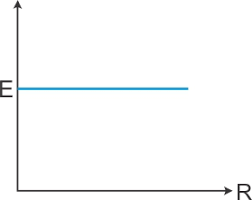
Emf of the cell does not depend upon external resistance.
Graph between Potential difference and Resistance

V = I R
V = ( E / R + r ) R
V = [ ( E / R ) / ( 1 + r / R ) ] R
V = E / ( 1 + r / R )
Graph between Potential difference and current

E = V + I r
V = E – Ir
y = m x + c
V = -Ir + E
Combination of Identical Cells
Series Combination of Identical Cells

Two cells are said to be connected in series combination when negative terminal of one cell is connected to positive terminal of other cell. Let E be emf of each cell
r be internal resistance
R be external resistance
n be number of cells connected
Total Emf = n E
Total resistance = n r + R
Total Current = Total Emf / Total resistance = n E / n r + R
I = n E / n r + R
→ If R >>>> r., i.e, R >>> n r
Means it is fresh cell
Internal Resistance will be neglected
I = n E / R
Conclusion : Fresh cell should be connected in series in order to increase current
→ If n r >>>> R
Means it is used cell
External Resistance will be neglected
I = E / R
Conclusion : Used cell should be connected in Parallel combination
Parallel Combination of Identical Cells

Let m number of identical cells each of emf E and internal resistance are connected to external resistance R
In Parallel combination, positive terminal of all the cells are connected at one point and their negative terminals to other point.
1 / rp = 1 / r + 1 / r ….. upto n terms
rp = r / n
Total resistance in Circuit = (R) + ( r / n )
In Parallel combination, effective emf of the circuit remains equivalent to emf of a single cell since only size of electrode increases in parallel combination. No change in emf takes place.
Total Current = Total Emf / Total resistance = n E / r + n R
I = n E / r + n R
→ If r >>> n R
Internal resistance >>> External Resistance then n R is neglected
I = n E / r
Output becomes n times
→ If n R >>> r
External Resistance >>> Internal resistance then r is neglected
I = E / r
Mixed Grouping of Identical Cells
In mixed grouping some cells are connected in series in a row and number of similar rows of cells are connected in parallel.
Let n be number of cells in series
Total internal resistance = n E
m be the number of rows of cells in parallel
Total internal resistance of all the cells will be given as
1 / r p = 1 / n r + 1 / nr + 1 / n r ….. upto m terms
r p = n r / m
Total resistance in the circuit = R + n r / m
Effective emf of all the cells = n E
Total Current = Total Emf / Total resistance = n E / ( R + n r / m ) = m n E / m R + n r
The current I will be maximum when m R + n r will be minimum.
[ (√ m R) 2 + (√ n r) 2 – 2 √ m n R r ] + 2 √ m n R r = minimum
( √ m R – √ n r)2 + 2√ m n R r = minimum
√ m R – √ n r = 0
√ m R = √ n r
m R = n r
R = n r / m
Current will be maximum if external resistance of cell is equal to net internal resistance of all the cells
Series Combination of Non Identical Cells

Let E1 be Emf of First Cell
Let E2 be Emf of Second Cell
r1 , r2 be internal resistances
V1 , V2 be potential difference applied across the cells
V = V1 + V2
V1 = E1 – I r1
V2 = E2 – I r2
V = E1 – I r1 + E2 – I r2
V = E1 + E2 – I ( r1 + r2 )
V = Eeq – I req
Parallel Combination of Non Identical Cells
Let Ieq = I1 + I2
Eeq – V / r eq = ( E1 – V / r1 ) + (E2 – V / r2 )
Eeq – V / r eq = E1 / r1 – V / r1 + E2 / r2 – V / r2
Eeq – V / r eq = E1 r 2 + E2 r 1 / r 1 r 2 – V ( r1 + r2 / r1 r2 )
V ( r1 + r2 / r1 r2 ) = E1 r 2 + E2 r 1 / r 1 r 2 – I
V = (E1 r 2 + E2 r 1 / r 1 r 2) ( r1 r2 / r1 + r2 ) – I ( r1 r2 / r1 + r2 )
V eq = Eeq – I req
→ Eeq = E1 r 2 + E2 r 1 / r 1 + r 2
r eq = r1 r2 / r1 + r2
→ Relation between E eq and r eq
Eeq = ( E1 r 1 + E2 r 2 ) r eq
Kirchhoff’s Rules
Kirchhoff’s First Rule
According to Kirchhoff’s first rule sum of the total current for a junction is equal to zero mean net current entering is equivalent to net current leaving the group.
It is based on law of conservation of charge
∑ I = 0
It is also called current rule or junction theorem.
Kirchhoff’s Second Law
According to Kirchhoff’s voltage law, the sum of the total potential and emf for a closed loop is always zero.
∑ E + ∑ V = 0
Wheatstone Bridge
It helps in comparing resistances.
Wheatstone bridge is defined as arrangement of four resistances in the form of bridge and is used for determining one unknown resistance in terms of other three known resistances.
Wheatstone bridge states that if four resistances P , Q , R and S are connected to form a bridge then bridge is considered to be balanced
P / Q = R / S

In loop ABDA
– I1 P – Ig G + ( I – I1 ) R = 0
– I1 P – Ig G + I R – I1 R = 0
Ig = 0
– I1 P + I R – I1 R = 0
(I – I1 ) R = I1 P … (i)
In loop BCDB
– ( I1 – Ig ) Q + (Ig + I – I1 ) S + Ig G = 0
Ig = 0
– I1 Q + Ig G + Ig S + IS – I1 S = 0
– I1 Q + ( I – I1 )S = 0
( I – I1 )S = I1 Q … (ii)
Dividing equation (i) by (ii)
(I – I1 ) R / ( I – I1 )S = I1 P / I1 Q
∴ P / Q = R / S
→ It remains unaffected by the presence of internal resistance of the source.
→ It can not be used to measure very high or low resistances.
→ When resistance in four arms of bridges are same then wheat-stone bridge becomes quiet sensitive.
Note : If the position of cell and galvanometer are interchanged in a balanced wheat-stone bridge then balance point remains same.
When galvanometer shows only one sided deflection then error is said to be end error.
Meter Bridge or Slide Wire Bridge
It is a practical form of wheatstone bridge and works on the principle of balanced wheat stone bridge.

Let P be resistance of length l1
Q be resistance of length ( 100 – l1)
R / S = l1 / 100 – l1
The connection between resistors in a meter bridge is made of thick copper strips because the resistivity of copper wire is very low. As the connections are thick so area becomes larger and resistance of wire is almost negligible.
It is generally preferred to obtain balance point in the middle point of meter bridge wire since it improves the sensitivity of meter bridge.
Potentiometer
The potential difference between any two points in an electrical circuit is measured accurately by an instrument commonly known as potentiometer.
It is also used for comparing emf of two cells and for measuring internal resistance of the cell.
Principle: The potential difference across any length of steady current carrying wire of uniform cross section is directly proportional to the length of that portion of wire.
Sensitivity: The smallest measured value with the help of potentiometer indicates highest sensitivity. For a potentiometer to be sensitive, length should be more and potential gradient should be less.
Internal resistance can also be measured by potentiometer using the formula stated below:
r = (l1 / l2 – 1 ) R
Here l1 and l2 are balancing length.
We would love your reading of Electric Charges and Fields, Electrostatic Potential and Capacitance, Magnetism and Matter, Electromagnetic Induction , Moving Charge and Magnetism, Current Electricity for scoring better and having deeper understanding of the chapters.
Do share the post if you liked the notes of Current Electricity Notes. For more updates, keep logging on BrainyLads

Electromagnetic Induction Class 12 | Notes | Chapter 6 | Physics | CBSE |

Moving Charge and Magnetism Class 12 | Chapter 4 | Physics | CBSE |


All my doubts regarding this chapter are cleared after reading your notes . Thanks for informative content