Moving Charge and Magnetism Class 12 | Chapter 4 | Physics | CBSE |
Table of Contents
Moving Charge and Magnetism Class 12 | Chapter 4 | Physics | CBSE |
Moving Charge and Magnetism
The space around a current carrying conductor in which its effect can be felt is defined as magnetic field.
Biot – Savart’s Law
It is also known as Laplace’s law. This law is used to determine the strength of magnetic field at any point due to a current carrying straight wire .

According to Biot Savart’s law;
Let dl be small element length of wire
I be current in wire
r be distance from wire to the point where we have to find Magnetic field
dB ∝ I dB ∝ dl dB ∝ sinθ dB ∝ 1 / r2
Combining all these factors, we get
dB ∝ I dl sinθ / r2
dB = K (I dl sinθ / r2 )
Here, K is constant of proportionality
In SI unit K = μo / 4π
In CGS system K = 1
Similarities and Dis-similarities between Biot Savart’s Law for Magnetic Field and Coulomb’s Law for Electrostatic Field
Similarities :
- In Both the laws, field varies inversely proportional to the square of the distance from the source to the point of observation.
- Both the fields obey superposition principle.
- The magnetic field is linearly related to its source namely the current element I.dl and electric field is also linearly related to its source., i.e, Charge q
Dis-similarities :
- Electrostatic field is produced by a scalar quantity named as charge q whereas magnetic field is produced by a vector quantity known as current element I. dl
- Electrostatic field at a point is independent of angle θ whereas magnetic field is angle dependent.
Magnetic Field due to a Straight Current Carrying Wire
Let XY be a straight current carrying conductor
I be current in the conductor
P be a point at distance a from straight current carrying conductor where we have to find magnetic field
A small current element of I dl of straight wire conductor at O
dB be small magnetic field
According to Biot Savart’s law

→ If Conductor’s length is infinity
B = (μo / 4π) ( I / a) ( 2 sin 90°)
B = (μo / 4π) ( 2 I / a)
→ If Conductor’s length is infinity on one side
B = (μo / 4π) ( I / a) ( sin 90° + sin 0° )
B = (μo / 4π) ( I / a)
Magnetic Field at the Centre of Current Carrying Loop
Let the radius of circular coil be r
I be the current flowing in the circular coil
dl be small element length
dB be small magnetic field due to length dl
From Biot Savart’s law

If Circular coil contain N number of turns

Magnetic Field at a Point on Axis of Circular Coil Carrying Current

Let radius of circular coil be r
Consider the plane of paper perpendicular to the plane of the coil
Current flowing in the loop be I
P be a point at distance a on axis of circular coil from its centre O
According to Biot Savart’s law the magnitude of magnetic field at P due to current element I dl will be given as

At point P, small magnetic field can be resolved as dB cos Φ and dB sin Φ; dB cos Φ cancel each other and dB sin Φ gives the net effect.

If the coil contain n number of turns

At centre of coil., i.e, when a = 0
Ampere’s Circuital Law
Ampere’s Circuital law states that the amount of the magnetic field around a closed loop is equal to total amount of an electric current enclosed by the loop.
It can also be defined as the total magnetic field enclosed by a loop over a closed path is equal to μo times current flowing through the conductor.
∫ B. dl = μo I
Here I is the net current threading the closed path and μo is absolute permeability of the space.
Let XY be a long straight and thin conductor

I be current flowing in the conductor
The magnetic field generated around the conductor is represented by concentric circles which are perpendicular to the plane of paper with their centre lying on the conductor
Let P be a point at perpendicular distance r from conductor
Magnitude of magnetic field at P is given as
B = (μo / 4π) (2I / r ) = μo I / 2π r
Consider a small element of length dl . The direction of B and dl are same and hence angle between them would be 0°.
∫ B . dl = ∫ B dl cos0° = B ∫ dl = (μo I / 2π r ) ( 2π r )
∫ B . dl = μo I
This is required expression for ampere circuital Law.
Solenoid
A current carrying copper wire having many turns and an insulated material inserted between it is defined as solenoid. It is a device which generates magnetic field due to passage of current.
Each and every part or turn of solenoid can be considered as a magnet.
The total magnetic field would be the vector sum of magnetic field due to current through all the turns in the solenoid.
Magnetic Field Due to a Solenoid

Let n be number of turns per unit length of solenoid
I be current flowing through the solenoid
Let a rectangular amperian loop PQRS is placed near the middle of a solenoid
Path QR and SP are tangential to the axis of solenoid, the magnetic field along QR and SP is zero. Hence, path QR and SP would not contribute to magnetic field B.
The component of magnetic field along RS is also zero.
Thus According to Ampere Circuital Law
PQRS ∫B. dl = PQ∫B. dl + QR∫B. dl +RS ∫B. dl + SP∫B. dl
PQRS ∫B. dl = PQ∫B. dl
PQRS ∫B. dl = PQ∫B dl cos 0° [ B ll dl ]
PQRS ∫B. dl = μo I x Number of turns
B ∫ dl = μo I x n L
B L = μo I x n L
B = μo n I or B = μo N I / L
Note: Outside the Solenoid, the magnetic field is negligibly small as compared to that inside a solenoid.
Toroid
If a Solenoid is bent in the form of a circle it forms a toroid.
Toroid can also be defined as a hollow circular ring on which large number of insulated turns of metallic wire are closely wound.
Magnetic Field Due to a Toroid

Let n be the number of turns per unit length
I be the current passing through toroid
B be the magnetic field due to current in the toroid
Inside the toroid (r < R)
At position 1 ; draw an amperian loop such that r < R
∫ B .dl = μo x current enclosed by loop 1
∫ B .dl = μo x 0
B = 0
Along the loop 2,. i.e, when r = R
∫ B .dl = μo x Total current
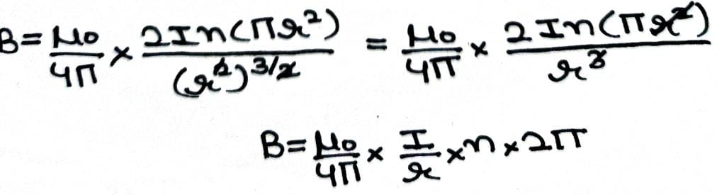
∫ B .dl = μo x n x 2πr x I
B ( 2πr ) = μo x n x 2πr x I
B = μo n I
This is the required expression for magnet field due to a toroid
Outside the Toroid ( r > R)
∫ B .dl = μo x current enclosed by loop 3
∫ B .dl = μo x 0
B = 0
Note : Inside and Outside the Toroid (In the empty space); magnetic field is zero.
Torque on a Current Carrying Coil in a Uniform Magnetic Field

Let PQRS be a rectangular coil of length l and breadth b is suspended in a uniform magnetic field.
Let PQ = RS = l
QR = SP = b
I be the current flowing through the coil
F1 , F2 , F3 and F4 be the forces acting on four current carrying arms PQ , QR , RS and SP respectively.
Forces F2 and F4 are equal in magnitude and opposite in direction, they cancel each other.
F1 = F3 = I lB sinθ [θ = 90°]
F1 = F3 = IlB
Torque = Force x perpendicular distance
Torque = Force x arc of couple
cosθ = ST / SP = ST / b
ST = b cosθ (Arc of couple)
τ = I l B x b cosθ
τ = I A B cosθ
Here θ is angle between rectangular loop and magnetic field .
θ + α = 90°
θ = 90° – α
τ = I A B cos (90° – α )
τ = I A B sinα
Here α is angle between normal and magnetic field
→ If the coil contain N number of turns
τ = N I A B sinα
→ If the angle between rectangular loop and magnetic field is 0°.
τ = I A B cos 0° = I A B
Torque would be maximum
→ If the angle between rectangular loop and magnetic field is 90°.
τ = I A B cos 90° = 0
Torque would be minimum
Moving Coil Galvanometer
Galvanometer is an electro-chemical instrument used for detecting and indicating electric current. It is a sensitive electromagnetic device which can measure very low current even of the order of few micro amperes. Galvanometer works as an actuator by producing a rotatory deflection in response to electric current flowing through coil in a constant magnetic field.
Principle
When a current carrying coil is placed in uniform magnetic field, it experiences torque.
Theory

Let N be the number of turns
I be current flowing into the coil
B be the magnetic field
As we know, rectangular coil carrying current when placed in external magnetic field experiences torque whose magnitude is given as τ = NIAB sinα
Since the magnetic field is radial., i.e, plane of the coil is parallel to the magnetic field α = 90°
[ sin 90° = 1]
τ = NIAB sin 90° = NIAB
Due to the presence of this torque, coil rotates and hence a phosphor bronze wire is twisted. Thus, a restoring torque comes into play in the phosphor bronze wire. This restoring torque would try to rotate the coil back to its initial position.
Let θ be the twist produced in phosphor bronze wire
k be the restoring torque per unit twist of phosphor bronze wire
τ = k θ
Now at equilibrium position of coil
Deflecting Torque = Rotating torque
NIAB = k θ
I = k θ / NAB
[ k / NAB = G = Galvanometer constant ]
I = G θ
I ∝ θ
Deflection produced is proportional to current flowing through the galvanometer
Construction
- Permanent Magnet
- Soft Iron Core
- Rectangular Coil
- Torsion Head
- Phosphor Bronze Wire
- Elastic Spring
Sensitivity of Galvanometer
Current Sensitivity : It is defined as ratio of deflection in galvanometer when unit current flows through it.
Let θ be deflection in the galvanometer
I be current flowing through it
IS = θ / I = nBA / k
Unit of current sensitivity is radian Ampere -1
Voltage Sensitivity: It is defined as deflection in galvanometer when unit voltage is applied across two terminals of the galvanometer.
Let θ be deflection in the galvanometer
V be voltage applied across two terminals of galvanometer
VS = θ / V = θ / IR = nBA / kR
Unit of voltage sensitivity is radian Volt-1
Note: A Galvanometer is said to be very sensitive when it shows very large deflection even when a small current is passed through it.
Question : Why a Galvanometer cannot be used to measure current in a given circuit?
Answer: This is due to following reasons:
- Galvanometer is very sensitive. It gives full scale deflection even with a quite small current.
- Galvanometer has to be connected in series in circuit in order to measure the current. Since its resistance is large, its presence will decrease the net current in circuit.
Question : The material of the wire used for suspension of the coil in the moving coil galvanometer has some special properties. State these properties.
Answer: The properties of the material used for suspension of coil in moving coil galvanometer are as follows:
- It should have high tensile strength.
- It should be a non magnetic substance.
- It should have low temperature coefficient of resistance.
- It should have low torsional constant.
- It should be good conductor of electricity.
Question : What are the main functions of soft iron core used in a moving coil galvanometer?
Answer: This makes the magnetic field radial.
This increases the strength of magnetic field due to crowding of magnetic field line of force through soft iron core, which as a result increases the sensitiveness of the galvanometer.
Question : What are the advantages of Moving Coil Galvanometer?
Answer: Advantages of moving coil galvanometer are stated below:
- Extremely sensitive device as it can detect very small current
- External magnetic field does not affect its working.
- It can be converted into ammeter by connecting a shunt in parallel with it.
- It can be converted into voltmeter by connecting a high value resistance in series with it.
Question : How can we achieve radial magnetic field in moving coil galvanometer?
Answer: It can be achieved by using soft iron core within it and by properly cutting the magnetic pole pieces into shape of concave faces.
Conversion of Galvanometer into Ammeter
By using a very low value resistance in parallel with galvanometer, galvanometer can be converted into ammeter
The very low value resistance which is connected in parallel with galvanometer in order to form ammeter is commonly known as shunt. It protect the galvanometer from the strong current.
Let I be the maximum current that can be measured by galvanometer
A shunt of resistance S is connected in parallel with galvanometer, so that out of the total current I , a part Ig pass through the galvanometer and I – Ig flows through the shunt.
We know, in parallel combination voltage remains same

Potential across shunt = Potential across Galvanometer
Ig G = ( I – Ig ) S
S = ( Ig / I – Ig) G
Note: An ideal ammeter has zero resistance.
This should be the value of shunt resistance S to be connected in parallel so as to convert it into ammeter of the range 0 to I ampere.
The effective resistance of the ammeter will be given as
Rp = GS / G + S
Conversion of Galvanometer into Voltmeter
A galvanometer can be converted into voltmeter by connecting a very high value resistance in series with galvanometer.

Let V be the potential difference that has to be measured by galvanometer.
Current Ig flows through the galvanometer
Total resistance of voltmeter will be given as G + R
From Ohm’s law Ig = V (G + R)
R = (V / Ig ) – G
This should be the value of resistance R which has to be connected in series
Note : The resistance of an ideal voltmeter is infinity
We would love your reading of Electric Charges and Fields, Electrostatic Potential and Capacitance, Magnetism and Matter, Electromagnetic Induction , Moving Charge and Magnetism, Current Electricity for scoring better and having deeper understanding of the chapters.
Do share this post if you liked it. For more updates, keep logging on BrainyLads

Current Electricity Notes | Chapter 3 | Physics | Class 12 | CBSE | Term 1 |

Electromagnetic Induction Class 12 | Notes | Chapter 6 | Physics | CBSE |


systematic and up to mark informative