Electricity Class 10 | Science | CBSE | Term 2 | Chapter 1 |
Table of Contents
Electricity Class 10 | Science | CBSE | Term 2 | Chapter 1
Introduction
Electricity is the most important source of energy in our times as it is used at various places like in our homes, industry, transport etc. The concept of electricity has actually proved that charges can be produced and also they can flow and this flow of charges produces electricity. To understand electricity, we should know about electric charges.
Electric Charge
Frictional force is a contact force which comes into account when two objects are rubbed against each other. For example: Rubbing of glass rod with silk i.e. when the glass rod is rubbed with silk, then there will be flow of charges between the two bodies. Due to this friction, concept of charges were introduced and coulomb was the scientist to introduce about the charges .
Basically, there are two types of charges:
- Positive charge : removal of electrons from a neutrally charged object
- Negative charge : addition of electrons to a neutrally charged object
“Opposite charges always attracts(moving towards) each other and similar charges always repel(move away) each other. “
SI unit of charge is coulomb which is denoted by ‘C’. One coulomb of charge can be explained as the charge which exerts a force of 9*109 Newtons on a charge which is placed at a distance of 1 metre from another equal charge. since matter consists of electrons and protons . Electrons and protons are negatively and positively charged respectively. An electron has a negative charge of 1.6 *10-19 C . Number of electrons in one coulomb of charge is 6.25* 1018.There are various types of substances, there are some substances in which charge can flow easily but in others they cannot. So substances can be further divided into two :
Conductors
These are the substances through which charges can flow i.e. electricity can flow are known as conductors. For example : all the metals like silver, aluminum, copper etc. are conductors. Metal alloys can also be the conductors but with low conductivity than metals .The presence of free electrons in a substance makes it a conductor of electricity.
Insulators
These are the substances through which charges can not flow are known as insulators. For example: glass, rubber, plastic, cotton, mica, ebonite etc. are all insulators as they do not allow electricity to pass over them. The presence of electrons in insulators are tightly bound by the nucleus hence are not free to move, therefore charges cannot flow.
Electricity can be classified into two categories:
- Static electricity: static means “at rest”, this is the type of electricity in which charges cannot move.
- Current electricity: this is the type of electricity in which charges are in motion and produce an electric current.
Related
Electric Potential
When electric charges are kept at some distance to each other then a charge will form an area around itself, and that area upto which effect of charge can be felt by another charge which is placed at some distance is known as electric field. In that electric field small positive charge will experience some force due to another positive charge and work has to be done to move that test charge against the force of repulsion.
Electric potential can be defined as the work done in bringing a unit positive charge from infinity to that point. It is denoted by ‘V’.SI unit of electric potential is volt. 1 volt can be defined as 1 joule of work is done in moving a 1 coulomb of charge from infinity to that point.
Potential Difference
The difference in electric potential between two points is known as potential difference i.e. amount of work done in moving a unit charge from one point to another point.
Numerically, potential difference = Work done/quantity of charge moved OR V=W/Q
- Potential difference is measured using ‘Voltmeter’
- A voltmeter has high resistance so that it takes negligible amount of electric current from the circuit.
- Voltmeter is always connected in parallel with the circuit.
- ‘Voltage’ is the other name of potential difference.
Q1. How much work is done in moving a charge of 2 coulombs from a point at 118 volts to a point at 128 volts ?
Answer : we know that,
Potential difference = work done/ charge moved
Here, potential difference,V=128-118 = 10 volts
and charge moved , Q= 2 coulombs
putting these values in above formula, 10=W/2 OR W= 20 joules
Electric Current
Whenever there are two charged objects connected by a metal wire held at some potential to each other, then the charges will flow from higher potential to lower potential till they both are at same potential and this flow of charges(electrons) in a metal wire said to be an electric current .’potential difference between the ends of wire is responsible for the charges to flow in the wire’.
The electric current is the flow of electric charges(electrons) in a conductor such as metal wire. electric current is denoted by ‘I’ . If a charge of Q coulombs flows through a conductor in ‘t’ seconds then magnitude of electric current be given as : I = Q/t
- SI unit of electric current is known as ‘Ampere’ which is denoted by ‘A’ .
- 1A=1C/1s, When 1 coulomb of charge flow through any conductor in 1 second , then current is said to be 1 ampere
- Smaller unit of ampere is “milliampere”. 1mA= 10-3A
- Current is measured by using the instrument called “Ammeter”.
- Ammeter is always connected in series with the circuit .
- An ammeter has very low resistance so that it may not change the value of current.
Q2. An electric bulb draws a current of 0.25 A for 20 minutes. Calculate the amount of electric charge that flows through the circuit.
Answer : Here, current, I = 0.25 A
time, t = 20 minutes = 1200 seconds
since I=Q/t
OR
0.25 = Q/ 1200
Q= 0.25 * 1200 C =300 C
- Basic reason of electric current to flow is the potential difference between two end points of a circuit. So, to get a continuous flow of electric current, it is necessary to maintain the potential difference between two ends of a conductor by using a cell or a battery between the ends of conductor.
- Potential difference is maintained by cell due to the chemical reactions going inside cell and this drives the current in the circuit.
- For example : A single dry cell consists of potential difference of 1.5 volts between the two positive and negative terminal and when this is connected to any light bulb through wires then electric current starts to flow through the wires due to which bulb glows .
- The conventional direction of electric current is from positive terminal to negative terminal whereas direction of electronic current(current in the direction of electrons) is from negative terminal to positive terminal.
- When the wire is not connected with the help of potential difference then the electrons present in the conductor (or wire) moves in random or zigzag direction BUT when a source of potential difference i.e. cell or battery is connected to the conductor then an electric force will start acting onto the electrons and all the electrons will start moving from negative terminal to positive terminal and this flow of electrons will constitute electric current.
Electric Circuits
A continuous conducting path which consists of wires and other resistances ( like electric bulb etc) and a switch between the two terminals of a cell or a battery along which electric current can flow is called a circuit.

Circuit symbols

- Battery is a combination of two or more cells connected in series
- resistance which can be changed accordingly is known as variable resistance or ‘rheostat’
- instrument used to measure current ‘ammeter’
- instrument used to measure potential difference ‘voltmeter’
- instrument used to just detect the current ‘galvanometer’
- when the switch is open ⇒ circuit breaks ⇒ no current will flow
- when the switch is closed ⇒ circuit made ⇒ current will flow .
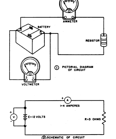
Circuit Diagram
A basic diagram which indicates how components in the circuit should be arranged or connected by using electrical symbols for different components in an electric circuit is known as circuit diagram.
Ohm’s Law
It tells about the relationship between current and potential difference. It states that “At constant temperature and in the absence of any strains, the current flowing through any conductor is directly proportional to voltage or potential difference applied across its ends.
I α V where I is the electric current flowing through the conductor and V is the potential difference across its ends.
OR
V α I ⇒ V = IR Where R is a constant to replace symbol of proportionality and it is known as resistance.
In Words, potential difference = current * resistance
Therefore, the ratio of potential difference applied between the ends and current flowing through the circuit is known as resistance.
Conclusion from the above relation :
- Current is directly proportional to potential difference i.e. more the potential applied between the ends more will be the current flowing through the circuit
- Current is inversely proportional to resistance i.e. more the resistance in the conductor less will be the current flowing through the circuit.
Note : Potential difference (V) between ends of conductor is doubled , current (I) flowing through the circuit will also be doubled
- If the resistance is doubled , then current will be halved.
Graph between V and I : This means to draw a graph between potential difference applied across the ends and current flowing through the circuit. V ( potential difference) is plotted on x-axis and I (current) is plotted on y-axis.
- A straight line graph is obtained when the two of the quantities which has to be taken on the graph are directly proportional to each other
- whenever the current-potential difference graph is straight line means current is directly proportional to potential difference. Hence, it verifies ohm’s law.
- To calculate resistance from the graph: Slope of ‘current- potential difference ‘ graph will give the value for resistance of the conducting wires from the graph.
Q.3 The values of current I flowing through the a coil for the corresponding values of the potential difference V across the coil are shown below :
I (amperes) : 0.1 0.2 0.3 0.4 0.5
V (volts ) : 0.5 1.0 1.5 2.0 2.5
Plot a graph between V and I and calculate the resistance of coil
ANSWER :

Hence , resistance = potential difference/ current
R= V / I OR R = 0.5 / 0.1 = 5 ohms ( slope of the given graph )
Resistance : since, electric current is flow of charges(electrons) in conductor. when these electrons move from one side to another side of the conductor then they will collide with many electrons in between the conductor. due to this collision of electrons with one another, there will be some restriction or opposition in the flow of electrons and the property of conductor due to which there is an opposition to the flow of electric current through the circuit. This property is known as resistance. Numerically, R=V/I
- SI unit of resistance is ohm
- 1 ohm can be defined as when 1 V of potential difference is applied across the ends and 1 A of current is flowing through the circuit then resistance in the circuit is said to be 1 ohm.
- Resistance of conductor depends upon :
- Length : resistance is directly proportional to length i.e. A long wire has more resistance than a short wire. Resistance, R α l where l is the length of the given conductor i.e. if length of the conductor is doubled then resistance will also get doubled.
- Area of cross-section of the conductor : resistance is inversely proportional to area of cross-section i.e. a thick wire has less resistance than a thin wire . Resistance , R α 1/A where A is the area of cross section i.e. when the area of cross-section is doubled , resistance will be halved.
- Nature of material of the conductor : resistance depends upon the nature of material of the conductor of which it is made. for example : consider two wires with constant length and area , of copper metal and nichrome alloy, then nichrome wire has more resistance than copper metal. Hence , resistance depends upon temperature!
- Temperature : resistance of pure metals increase with increase in temperature as due to increase in temperature, more will be the flow of electrons in the conductor hence more will be the resistance !
Q.4 An electric iron draws a current of 3.4 A from the 220 V supply line. What current will this electric iron draw when connected to 110V supply line ?
Answer : Firstly, resistance of electric iron can be calculated and then it can be used to calculate the current in case of 110V supply line.
step 1.
potential difference ,V = 220V
current , I = 3.4 A
resistance, R = V/I
R= 220/3.4
R = 64.7 Ω
step 2.
now, to find the current drawn by 110 V supply line :
R= V/ I
64.7= 110/ I
I , current = 110/64.7 = 1.7 A
On the basis of electrical resistance, every and each substance can be divided into three groups :
- Good conductors : these are the substances which have very low electrical resistance are known as good conductors. For example : copper and aluminum metals are good conductors of electricity..
- Resistors : these are the substances which have comparatively high electric resistance than good conductors are known as resistors . For example : alloys like nichrome, manganin etc.
- Insulators : these are the substance which have infinitely high electric resistance are known as insulators . For example ; rubber, wood etc.
Resistivity : since , resistance depends upon length and area as,
- Resistance of the conductor is directly proportional to length of the conductor : R α l
- Resistance of the conductor is inversely proportional to area of cross-section of the given conductor as : R α 1/A
By combining the relations above : R α l/A
R = ρl/A
Where ρ (rho) is a constant which is called as resistivity of the material of conductor.
- Resistivity can be defined as for a specific substance, resistivity is numerically equal to resistance(ρ=R) of the given conductor when the conductor (or any rod ) is 1 metre long and 1 square metre of area of cross-section.
- SI unit of resistivity is ohm-metre or Ω m
- resistivity of a substance does not depend upon length and thickness ( or area ) of the conductor but only depends upon nature of substance and temperature. Basically, resistivity of a substance is a characteristic property of the conductor.
- For example : Resistivity of copper is 1.69 * 10-8 ohm-metre . it means that , resistance of 1 m long and 1 square metre area copper rod has a resistance of 1.69* 10 -8 ohm
- resistivity of alloys are much higher than the resistivity of pure metal i.e. nichrome alloy has much more resistivity than copper and aluminum metal.
- The heating elements ( or heating coils ) of electric heating appliances such as electric iron are made of an alloy because resistivity of alloy is much more than any pure metal and secondly, an alloy does not undergo oxidation easily at high temperatures even.
- resistivity of i) metals : low ii) insulators : very high and does not change with temperature iii) semiconductors (silicon, germanium ) : in between those of conductors and insulators
Q5. A copper wire of length 2 m and area of cross-section 1.7 * 10-6 m2 has a resistance of 2 * 10-2 ohms. calculate the resistivity of copper .
Answer : since , resistivity ,ρ = R* A / l
given that , resistance , R = 2* 10-2 ohms
area ,A = 1.7 * 10-6 m2
length , l = 2 m
hence, ρ = 2* 10-2 * 1.7 * 10-6 / 2
ρ = 1.7 * 10-8 ohm-metre
thus, the resistivity of copper is 1.7 * 10-8 Ω m
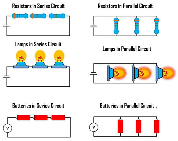
Combination of Resistances ( or Resistors ) : As current depends upon the resistance of the given conductor according to ohm’s law so to get the required current in the circuit( consist of resistance). Resistance need to be combined. Now there are the two ways to combine the resistance : (i) series (lengthwise) : when two or more resistances are connected end-to-end consecutively. (ii) Parallel : when two or more resistances are connected between the same two points.
- To increase the total resistance of the circuit , individual resistances will be connected in series.
- To decrease the total resistance of the circuit , individual resistances will be connected in parallel.

Resistances in Series : When the number of resistances are connected in series, then the combined value of the resistance is equal to sum of individual resistances i.e. R = R1 + R2 Suppose, R1 = 2 ohms and R2 = 4 ohms then R = 4+2 = 6 ohms
- Whenever there is a series connection between the resistors i.e. when the resistances are joined to terminals of a battery,then each resistance connected will have different potential difference across the ends and it will depend upon the magnitude of resistance.
- In the series connection of resistances , current will be same flowing through the whole circuit and each resistance
Resultant resistance of two resistance connected in series:

Above figure shows that the two resistances are connected one after another i.e. in series (R1 and R2) and a battery of V volts is connected to maintain the potential difference in the circuit which is necessary condition for flow of current in the circuit. As stated above, in series connection potential difference across each resistance will be different i.e. Across R1 it will be V1 and across R2 it will be V2 . Total potential difference , V = V1 + V 2 ……..(1) and total current going through the circuit is I which will be same in each resistor in the case of series connection.
According to ohm’s law, ‘potential difference = current * resistance ‘ numerically , V = IR ……….(2)
Since same current is flowing through each resistor but with different potential difference across each resistor.
V1 = I R1 ……….(3) and V2 = I R2 …………(4)
substituting values from equations (2) , (3) and (4) to (1) , we get :
IR = I R1 + I R2
IR = I ( R1 + R2)
cancelling ‘I’ from both sides ,
R = R1 + R2
This above relation is the combined resistance or equivalent resistance when the resistors are connected in series.
Resistance in parallel : when the number of resistors are connected in parallel , then the combined value of resistance is equal to sum of reciprocals of the individual resistances i.e. 1/R = 1/R1 + 1/R2 . Suppose R1 = 6 ohms and R2 = 12 ohms and to find out the combined resistance we have,
1/R = 1/6 + 1/12 ⇒ 1/R = 3/12
1/R = 1/4 or R = 4 ohms
- When there is a parallel connection between the resistors i.e. connected between the same two points then each resistance will have same potential difference across each resistor i.e. equal to the voltage of battery applied.
- Whenever there is a parallel connection between the resistors then current will be different across each resistor and depends upon the value of resistance and the current flowing through all the individual parallel resistances taken together is equal to the current flowing in the complete circuit.
Resultant resistance of three resistance connected in parallel :

above figure shows that resistors are connected parallel to each other i.e. connected between same two points (R1 , R2 , R3 ) and a battery of V volts is connected to maintain the potential difference between the resistors which is necessary condition for the flow of current in the circuit. As stated above, in parallel connection current across each resistance will be different i.e. across R1 it will be I1 and across R2 it will be I2 and across R it will be I3 . Total current flowing through the circuit, I = I1 + I2 + I3……….(1)
Total potential difference across the whole circuit and all the three resistances(R1 , R2 , R3 ) be ‘V’ , now by applying ohm’s law :
According to ohm’s law, ‘potential difference = current * resistance ‘ numerically , V = IR ……….(2)
Since same potential difference is maintained across each resistor but with different current flowing through each resistor.
I1 = V/R1 ………. (3) and I2 = V/R2 ……….(4)
substituting values from equations (2) , (3) and (4) to (1) , we get :
V/R = V/R1 + V/R2 +V/R3 or V[1/R] = V[1/R1 + 1/R2 + 1/R3 ]
now, we get :
1/R = 1/R1 + 1/R2 + 1/R3
Thus , if three resistances are connected in parallel , then their combined resistance i
s given by : 1/R = 1/R1 + 1/R2 + 1/R3
Q.6. In the given circuit diagram , find
- total resistance of the circuit
- total current flowing in the circuit
- the potential difference across R1
Answer : calculation of total resistance : To find out the total resistance of the circuit we need to know the resistances in parallel and series, as we can see from the above figure R2 and R3 are connected between the same two points i.e. they are in parallel to each other therefore, combined resistance in case of parallel resistance is given by ;
1/R = 1/R2 + 1/R3 or 1/R = 1/8 +1/12
1/R = 3+2/24 or 1/R = 5/24
R = 24/5 = 4.8 ohms
And this single resistance of 4.8 ohms is obtained in place of two parallel resistances which will be in series with resistor( R1 ) i.e. 7.2 ohms thus , combination(or resultant) of these two resistance can be calculated with the help of :
Total resistance : 7.2+4.8 = 12.0 ohms
Calculation of total current : Total potential difference = 6 volts
total current , I = ?
total resistance as calculated above = 12 ohms
now, according to ohm’s law : V = IR
6 = I *12 or I = 6/12
I =1/2 or 0.5 ampere or 0.5 A
therefore, total current flowing through the circuit is 0.5 A
Calculation of potential difference across R1 : To find out the potential difference across 7.2 ohms
since, R1 is in series with other two resistors hence, current across R1 is same as in the whole circuit. Therefore, current across R1,I =0.5 A
and R1 = 7.2 ohms
now, according to ohm’s law , we have : V = IR
V = 0.5 * 7.2 = 3.6 volts
Therefore, the potential difference across R1 be 3.6 volts.
- Whenever an electric circuit is being designed then one should consider whether a series or a parallel circuit is better for intended use.
- Series connected circuits are suitable for diwali lights or marriage functions so that all the bulbs are connected one after the another and can be controlled using only one switch.
- Parallel connected circuits are suitable for connecting bulbs in houses so that there will be a separate switch for each and every appliance.
Disadvantages of series circuit for domestic wiring :
- All the electrical appliances will only have one switch in series connection and because of that they cannot be turned on or off separately.
- If one electric appliance stops working in case of series connection due to some defect then all the electric appliances also stops working.
- in series connection , all the electric appliances do not get the same voltage(220V) but depends upon the value of resistance so the appliances get less voltage and hence do not work properly.
- The overall resistance of the circuit increases in case of series connection due to which the current from power supply is less.
Advantages of parallel circuits for domestic wiring :
- all the electric appliances will have different switches in parallel connection and because of that they can be turned on or off seperately.
- If one electric appliance stops working in case of parallel connection due to some defect then all the electric appliances will work normally.
- in parallel connection, all the electric appliances get the same voltage (220V) hence all the appliances will get same voltage and they will work properly.
- the overall resistance of the circuit decreases in case of parallel connection due to which the current from power supply is more.
Electric power : we know that rate of doing work is power. When an electric current flows across the conductor , electrical energy is being used for the flow of current and hence current is doing some work. therefore , electric power is the electrical work done per unit time.
numerically , Power = work done / time taken or P = W/T
- SI unit of electrical power is watt denoted by the letter ‘W’
- 1 watt can be defined as consumption of electric energy at the rate of 1 joule per second.
- watt is the small unit and for commercial purposes, bigger unit i.e. kW (kilowatt) is used.[1kW=1000W]
As we know that , power = work done/time taken or P = W/T ……(1)
since work done ,W by current I when it flows for time t under a specific potential difference of ‘V’ volts then , W = V*I*T joules …..(2)
substituting equation (2) in equation (1) , we get :
P = V*I*T /T joules per second or P = V*I watt ……(3)
where V = potential difference , I = current flowing through the circuit
therefore, ‘electric power = potential difference * current’ or ‘electric power = voltage * current ‘
if an appliance is maintained at a potential difference of 1 volt and in the device current is flowing to be 1 ampere then according to the equation(3) power is said to be 1 watt i.e. 1 watt = 1 volt * 1 ampere or 1 W = 1 VA ….
Some other formulae of calculating electric power
Power P in terms of I and R : as stated above, P = V*I
since, according to ohm’s law V = IR
then , P = I*R*R = I2 R…… (4)
where I = current flowing across the conductor
R = resistance of the given conductor
Power P in terms of V and R : as above , P = V*I
since, according to ohm’s law I = V/R
then, P = V*V/R = V2/R …….(5)
where V = potential difference maintained across each conductor
R = resistance of the given conductor
- from equation (5) power is inversely proportional to resistance at constant voltage thus, the resistance of high power devices is lesser than the low power devices.
- first formula for power : P = V * I
- second formula for power : P = I2 * R
- third formula for power : P = V2/R
- Power rating of electrical appliances : a power rating of 100 watts on the bulb means that it will consume electrical energy at the rate of 100 joules per second.
Q.7. An electric bulb is rated 220 V and 100 W. when it is operated at 110 V , the power consumed will be :
Answer : Case 1.
Power , P = 100 W
Potential difference , V = 220 V
Resistance , R = ?
since , using the third formula for power : P = V2/R
therefore , 100 = 220*220 / R or 100 = 48400/R
R = 484 ohms
now, Case 2.
power , P = ?
potential difference , V = 110 V
Resistance , R = 484 ohms ( as calculated since resistance will be same in an electric bulb )
therefore, P = V2/R ( using the third formula for power)
P = 110*110/484 or P = 12100/484
P = 25 W
Therefore, power consumed by an electric bulb with potential difference of 110 V will be 25 watts .
Formula for calculating Electrical energy :
as we have seen above , electric power = work done by electric current / time
since we know that according to law of conservation of energy : work done by electric current = electrical energy consumed
so, it can be taken as : power = electrical energy consumed / time taken
or ‘electrical energy = power * time’
or ‘E = P*t’
- The product of power and the time for which it has been used will be the electrical energy consumed by an electrical appliance.
- electrical energy consumed depends on the two factors : power rating of an appliance and time for which the appliance is being used .
- SI unit of electrical energy be ‘watt-hour'(Wh)
- One watt-hour can be explained as the amount of electrical energy consumed when an electric appliance of power 1 watt is used for 1 hour.
Commercial unit of electrical energy : kilowatt-hour
SI unit of electrical energy is joule and in actual, joule represents a smaller unit of energy and everywhere it can’t be used i.e. for large quantity of energy . For commercial purposes bigger unit i.e. kilowatt-hour is being used.
- one kilowatt-hour is the amount of electrical energy consumed when an appliance of power 1 kilowatt(or 1000 watt) is used for 1 hour.
- therefore, commercial unit of electrical energy : kWh
Relation between kilowatt-hour and joule :
1 kilowatt- hour is the energy consumption at the rate 1 kilowatt for 1 hour.
1 kilowatt-hour = 1 kilowatt used for 1 hour
or it can be taken as 1 kilowatt-hour = 1000 watt used for 1 hour
as we know that : 1 watt= 1 joules/second
or 1 kilowatt-hour = 1000 joules/second used for 1 hour
or 1 kilowatt-hour = 1000 joules/second used for 3600 seconds ( 1 hour = 3600 seconds )
1 kilowatt-hour = 3600000 joules ( or 3.6 * 106 J )
i.e. 1 kilowatt-hour is equal to 3.6 * 106 joules
Q.8. A current of 4A flows through a 12 V car headlight bulb for 10 minutes. How much energy transfer occurs during this time ?
Answer : since, Energy = power * time
or E = P * t ……(1)
Firstly , we need to calculate the power from the given values of current and voltage by using the first formula of power :
P = V * I
P = 12 volts * 4 amperes
power , P = 48 watts
or P = 48/1000 = 0.048 kilowatt
time , t = 10 minutes = 10/60 hours [ 1 hour = 60 minutes ]
now. to calculate the energy by using equation (1)
Energy = P * t
E = 0.048 * (10/60)
E = 0.48/60
Therefore , E = 0.008 kWh
thus, the energy transferred is 0.008 kilowatt-hour…
To calculate the cost of electrical energy consumed :
since, kilowatt-hour is the “unit” of electrical energy consumed for which one pays for the electric supply they are using.. like if one says that one unit of electricity can cost from 3 rupees to 7 rupees. therefore , it can be understood as 1 kilowatt hour of electrical energy will cost from 3 rupees to 5 rupees. The electricity meter in our homes tells about the consumption of electrical energy by us in kilowatt-hour. For example : in our homes , we use electrical appliances like electric bulbs, fans, electric bulbs, tube-lights, T.V., refrigerator , radio , electric iron etc. which consumes the electric energy at different rates depends upon the power of the electric appliance and the time it is being used and then total consumption of electrical energy by these electrical appliances has been calculated over a given period of time ( say 1 month ).
since, electricity is stated in terms of kilowatt-hour. so, firstly power consumed in watts by the electric appliances is converted into kilowatts by dividing total watts by 1000. then this kilowatts are changed to kilowatt-hour which is unit of electrical energy consumed by multiplying those kilowatts by the number of hours that particular electric appliances has been used which gives the total electric energy consumed in ‘kilowatt-hour’ hence the number of units of electricity consumed.
Q9. A bulb is rated at 200 V – 100 W . What is the resistance ? five such bulbs burn for 4 hours. what is the electric energy consumed ? calculate the cost if the rate is Rs. 4.60 per unit .
Answer : Calculation of resistance : since , voltage and power is given. therefore , we need to calculate the resistance by using third formula of power i.e.
P = V2/ R
100 = 200*200/R
or , R = 200*200/100 ⇒ R = 40000/100
R = 400 ohms
calculation of electrical energy consumed : the electric energy consumed in kilowatt-hours can be calculated by :
E = P * t
Power , P = 100 watts = 100/1000 kilowatts
P = 0.1 kilowatts
and , time , t = 4 hours
therefore , energy consumed by 1 bulb = 0.1 * 4 = 0.4 kilowatt-hour
and , hence energy consumed by five bulbs = 0.4 * 5 = 2 kilowatt – hour ( or 2 kWh )
thus , the total energy consumed is “2 kilowatt – hour ” or “2 units “.
calculation of cost of electrical energy : given that ,
cost of 1 unit of electrical energy = Rs 4.60
therefore , cost of 2 units of electrical energy = Rs 4.60 * 2
= Rs 9.20
Effects produced by electric current :
there are three important effects which can produce electric current :
- Heating Effect
- Magnetic Effect
- Chemical Effect
Heating Effect of Electric Current
This effect of electric current can be obtained by the transformation of electrical energy into heat energy. basically , heating effect of electric current means whenever an electric current is passed through a high resistance wire like an alloy (nichrome wire ) then that resistance wire becomes very much as hot and thus produces heat. This is known as heating effect of electric current . As mechanical energy is used to overcome friction and is converted to heat . Similarly , as electric current flows through a resistance wire . the role of ‘resistance’ in electronics here is similiar to role of ‘friction’ in mechanics.
suppose , a resistance wire offers opposition to the flow of current so work must be done by the current so that it keep flowing . now , work done by the current I to flow through a resistance wire ‘R’ for time ‘t’ . when an electric charge Q moves against a potential difference V , the amount of work done is :
W = Q/V …. (1)
since, current , I = Q/t
or Q = I *t …..(2)
from ohm’s law , we have :
potential difference , V = IR ….(3)
substituting values from equation (2) and (3) to equation (1) , we have :
W = I * t * I * R
then , W = I2 R t
by assuming that work done by all the electric appliances or consumption of electrical energy by the appliances is converted into heat energy. Hence , it can be supposed as :
Heat produced , H = I2 R t
this is also known as Joule’s law of heating.

The heat produced in a wire is directly proportional to :
- Square of the current : if the current is doubled, then with constant resistance and time , heat produced will become four times.
- Resistance of the wire : if resistance is doubled , then with constant current and time , heat produced will ajlso be doubled i.e if for a given period of time current is passed through any wire then heat produced will be more in high resistance wire than low resistance wire. Also heat produced will be more when resistances are connected in series than in parallel.
- Time (t) for which current is passed : if current is passed through a given wire for double the time , then heat produced will also be doubled in that case.
- All the appliances which run on electricity do not convert all the electric energy into heat energy.it is valid only for the electric appliances that are needed for the production of heat. For example : electric heater , electric geyser , hair dryer , immersion rod etc. when electric current is passed through any electrical appliances then most of the electrical energy is converted into heat energy. All the electrical heating appliances have a heating element in it made of high resistance wire (nichrome wire) which basically converts electrical energy into heat energy.
Q.9. Calculate the heat produced when 96,0000 coulombs of charge is transferred in 1 hour through a potential difference of 50 volts.
Answer : firstly, current can be calculated from the given data :
current , I = Q/t
I = 96,000/60*60 [ 1 hour = 60*60 seconds ]
I = 96000/3600
I = 26.67 A
now, by using ohm’s law : R = V/I
R = 50/26.67
resistance , R = 1.87 ohms
to calculate the heat produced , we get :
H = I2Rt
Heat produced , H = 26.67*26.67*1.87*60*60
H = 4788400 joules
or H = 4788.4 kJ
thus , the heat produced is 4788.4 kilojoules.
Applications of Heating Effect of Electric Current :
- Heating effect of electric current can be used in the working of electric iron , electric geysers , immersion rod , electric kettle , electric toaster , room heaters , water heaters , electric toaster etc. the temperature of the heating element which is being used for an electrical heating device when it becomes red-hot and glows is about 9000c basicaaly high resistance wire is only used low resistance wire cannot be used like copper which produces negligible heat in an appliance.
- Heating effect of electric current is used in electric bulbs for producing light where electric current passes through a very thin , resistance tungsten filament of an electric-bulb and filament becomes white-hot and emits light. Tungsten metal is used as filment of electric bulbs as it has a high melting points i.e. of 33800c.Electric bulb is filled with chemically unreactive gas ( like argon or nitrogen) because if air is present in the bulb then tungsten filament would burn up in oxygen of air.
- Heating effect of electric current is utilised in electric fuse i.e. for protecting household wires and most expensive electric appliances.A fuse is a short length of thin tin plated copper wire having low melting point. As we know, thin fuse wire has higher resistance than the rest of electric wirings in the house. when the current in the household wires exceeds too much it will melts and breaks the circuit. this prevents damage to the household electrical appliances.

Q.10. In a filament type light bulb , most of the electric power consumed appears as : Infrared Rays.
Do share this post if you liked this post Electricity Class 10. For more updates, keep logging on BrainyLads.

Magnetic Effects of Electric Current Class 10 Notes | Science |

Our Environment Class 10 Notes | Science | Term 2 | Questions |


Nice and very helpful 😊👍.